
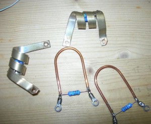
Spero di fare cosa gradita a tutti quelli che hanno bruciato il commutatore di banda del TL-922 pubblicando quest’articolo. Come si sa lo switch-band non è più disponibile da qualche tempo. Quindi o si butta il lineare o si trova una soluzione. Io dopo aver appreso in internet che qualcuno aveva sostituito il commutatore con dei relè sottovuoto ho deciso di imbarcarmi nell’avventura.
Mi sono procurato una dozzina di relè Kilovac HC-1.
I hope this article might be useful to all whom have burn the switch band of TL-922. As most of you knows the switch-band is no longer available in the market. When I learned from internet that someone has substituted the switch-band with a Vacuum-Relais I decided to try this. I bought a dozen of Kilovac HC-1.
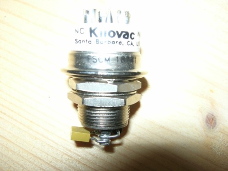 Fig. 1 – Kilovac HC-1
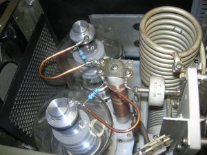
Questo è il colpevole della distruzione dei contatti del commutatore
This is the component to be blamed for the damages to the switch band.
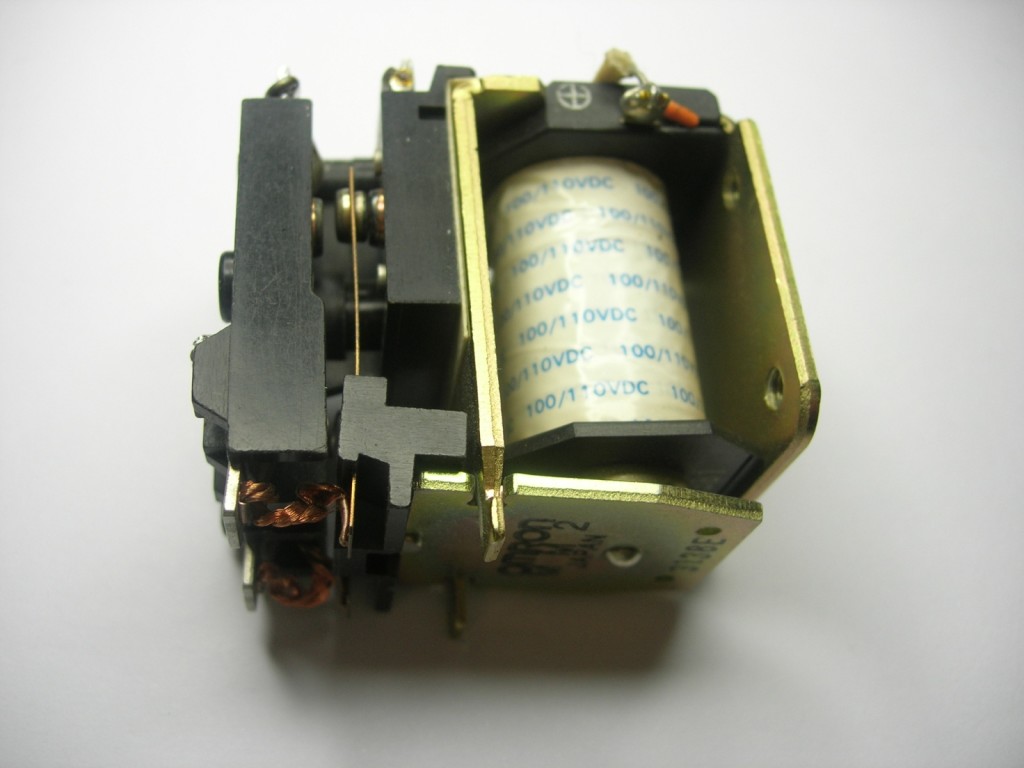 Fig. 2 – Relè d’antenna Antenna relais
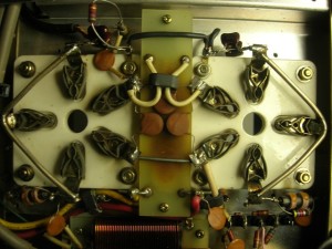
Infatti ho riscontrato delle bruciature sui contatti e, attuandolo a mano o notato che avveniva prima la chiusura del contatto di ingresso e poi quello di antenna. Quindi tutta la potenza del lineare non veniva immediatamente inviata al carico, con conseguente sfiamma tura e bruciatura dei contatti del commutatore di banda. Avessi cambiato subito questo relè con due sotto vuoto, probabilmente non avrei avuto problemi.
Consiglio vivamente di prendere in considerazione la sostituzione a tutti i possessori del TL-922 che lo usano. Non costa molto e risolve una buona parte dei problemi di quest’amplificatore.
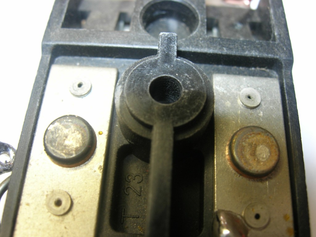 Fig. 3 – Visione contatti corpo relè – The contacts of the relè
I have noted some signs of burning on the contacts and when I tried to activate it manually I noted that firs the first it was closed the ingress contact and than that of the antenna. This men that the power was not sent directly where needed and the contacts of the switch band were burned. Had I changed this with two Vacuum-Relais I would have immediately resolved the problem.
I strongly recommend this changes to all owners of TL-922. It does not cost a lot and resolve many problems of this amplifier.
Ovviamente chi lo usa come sopramobile (a dire il vero un po’ pesante e ingombrante) avrà questi contatti ancora buoni ……. Accendetelo e date potenza poi ne parliamo Hi
Obviously of you do not use it will have no problems but just try to turn it on and you will see.
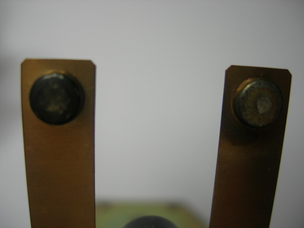
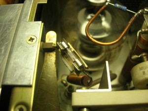
Fig. 4 – Altra visione contatti relè ma su parte mobile. – Another view of the contacts of the relè
Prima di tutto bisogna capire come avvengono le commutazioni delle bobine e delle capacità aggiuntive banda per banda. Dallo schema si può desumere. Ho marcato con lettere e numeri i collegamenti delle bobine e dei condensatori e ho tirato giù questa tabella.
First of all you will have to understand how it works the switch between the coils the additional capacity band by band. From the scheme it can be understood. I have marked with letters and numbers the connections of the coils and the condensers and drawn this table.
|
RELE’ |
160 | 80 |
40 |
20 | 15 |
10 |
|
|
1 |
1 | 0 | 0 | 0 | 0 | 0 | A |
|
2 |
1 | 1 | 0 | 0 | 0 | 0 |
B |
|
3 |
1 | 0 | 0 | 0 | 0 | 0 |
C |
|
4 |
1 | 1 | 0 | 0 | 0 | 0 |
D |
|
5 |
0 | 1 | 1 | 1 | 1 | 1 |
E |
| 6 | 0 | 0 | 1 | 1 | 1 | 1 |
F |
| 7 | 0 | 0 | 0 | 1 | 1 | 1 |
G |
|
8 |
0 | 0 | 0 | 0 | 1 | 1 |
H |
|
9 |
0 | 0 | 0 | 0 | 0 | 1 |
I |
| 1 = on | |||||||
| 0= off |
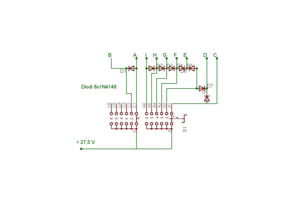
In the next image you will see the positioning of the relè on the basis of the numbers reported above. This has been obtained with a diodes matrix. You will find the scheme further below.
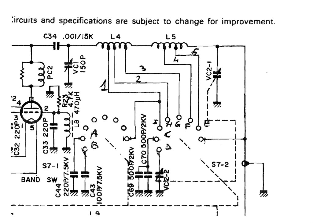 Fig. 5 – Parte dello schema interessata alla modifica
Le lettere e i numeri trovano riscontro nella tabella sopra. – Part of the scheme of the changes, You will find the letters and numbers in the table above
Dopo aver studiato come far stare i 9 relè all’interno del TL-922 (non è che ci sia spazio da vendere) ho cominciato a realizzare un supporto per 8 relè, il 9 è stato montato direttamente sul variabile di antenna.
After having thought how to accommodate the 9 relè inside the TL-922 ( there is not much room) I have built a support for 8 relè and the last one has been mounted on the antenna capacitor
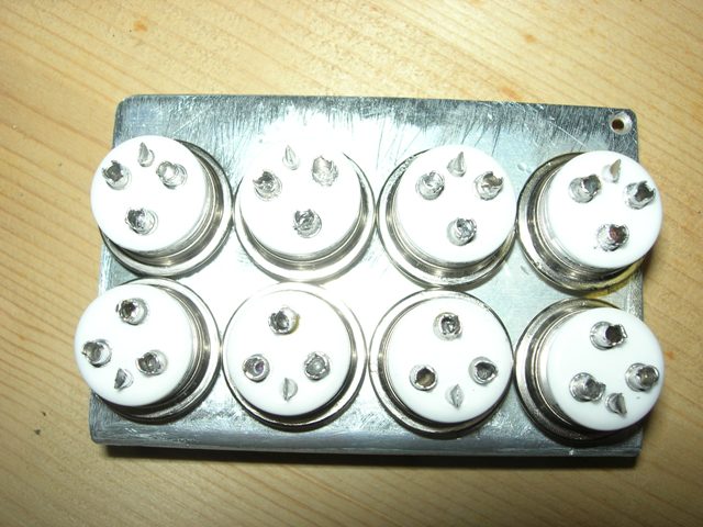
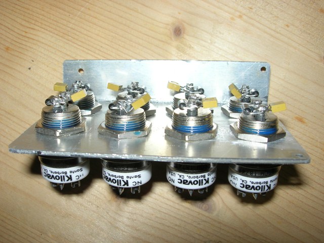
Fig. 6 – Supporto in alluminio – Alluminium support
Iniziamo a liberare spazio e a posizionare il commutatore per attuare il relè. Serve un commutatore 2 vie 6 posizioni di dimensioni adeguate. Io ho reperito questo:
We now start to gain some space to put the switch to turn on the relè. You will need a 2 way switch with 6 positions of adequate dimensions. I found this:
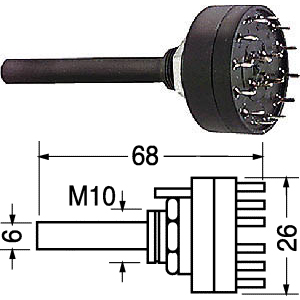 Fig. 7 Commutatore 2 vie 6 posizioni – Switch 2 way 6 position
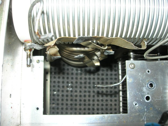
Fig. 8 Svuotamento vano commutazione. – Empty space for the switch
Bisogna rimuovere C43 e riposizionarlo come da Fig. 9 You have to remove the C43 as per picture no. 9
Fig. 9 – Riposizionamento C 43 – repositioning of C43
Rimane da rimuovere la piastra a L di separazione dello stadio d’ingresso, per montare il commutatore.
You now remove the L shape plate which divide the ingress stadium to mount the switch
 Fig. 10 – piastra rimossa – removed plate
Montaggio commutatore
Occorre tagliare l’alberino di misura e piegare i contatti, se non lo si fa si rischia che vadano a toccare i relè sul supporto di alluminio.
Mounting the switch
You need to cut the head of the switch and bend the contacts to avoid that they touch the aluminium support.
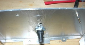
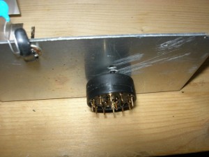
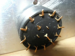
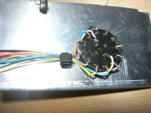 Fig. 11 – Montaggio commutatore – Switch mounting
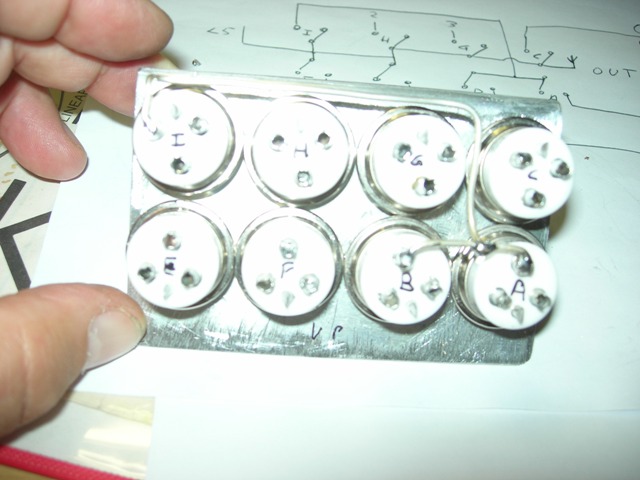
Fig. 12 – Marcatura relè – Marking the relè
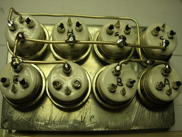 Fig. 13 – Cablaggio relè – Cabling of the relais
Ho costatato che nonostante la piegatura dei contatti del commutatore c’era il rischio di cortocircuito tra i relè e lo stesso, quindi ho incollato un pezzetto di plastica isolante sul lato alimentazione del supporto relè.
I have noted that despite the bending of the contacts of the switch there was still the risk of short-circuit I have therefore glued a piece of insulating plastic on the side of the electrical feed of the relè support
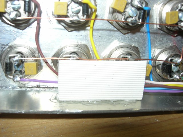 Fig. 14 – Isolamento di plastica – Plastic isolator
Saldare i fili di alimentazione dei relè, una massa comune e uno ogni positivo. Saldare anche i fili sul commutatore. Lasciarli sufficientemente lunghi per arrivare nel vano dove è montato lo zener .
In questa locazione ho inserito una basetta millefori con dei diodi 1n4148 per ottenere la matrice necessaria a gestire la commutazione come da tabella prima descritta. I fili vanno fascettati e fatti passare, dopo averli inguanati in un pezzetto di termo restringente, nello spazio tra la piegatura del panello frontale e la schermatura centrale. Cercare di stare più lontano possibile dai condensatori e dai loro collegamenti verso i relè. Questo per evitare fiammate, specialmente in 160m.
Weld the power cables of the relè, a common earth and one positive pole. Weld also the cable on the switch. The cable need to be long enough to arrive in the place were the zener is mounted. In this place I have also inserted a support base with 1n4148 diodes to obtain the necessary matrix to deal with the switch described in the table above. The cables need to be covered and sheathed in piece of heath-shrink then passed between the front panel and the central screen. You should try to put this as far as possible from the condensers and the cabling close to the relè, to avoid blazes at 160m.
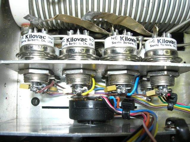 Fig. 15 – Posizionamento – Placing
Il supporto è fissato con due viti parker (qui si vede bene quella nera in basso a sinistra) io ho sfruttato un foro esistente sulla sinistra e ne ho fatto un altro a destra. E’ importante avere la piegatura del supporto verso il commutatore, altrimenti non si riesce a saldare i collegamenti alle bobine.
The support has been fixed with two parker screws (you can see the black one on the left). I have used the existing hole on the left and made another one on the right. It is important that the support is folded towards the switch, otherwise you cannot weld the connection to the coils.
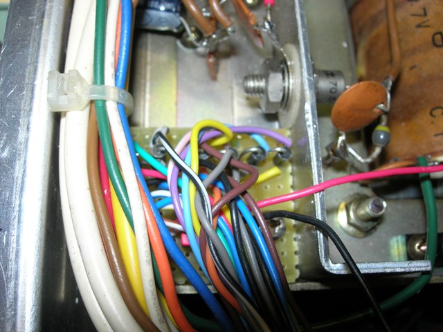 Fig. 16 – Posizione basetta diodi – Position of the diodes base
L’alimentazione è a 27,5 V per compensare in parte la caduta di tensione sui diodi. Non si causa nessun problema ai relè. Anche il relè “E”, che in posizione 10m è alimentato con circa 24 V funziona perfettamente.
Power is 27,5 V to compensate the fall of tension on the diodes. It does not create any problem to the relè. Also the relè “E” at position 10m is powered at about 24V and works perfectly.
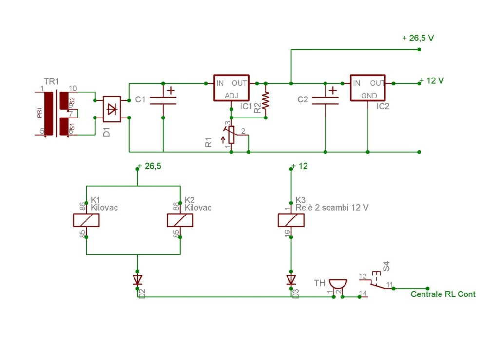
Lista componenti alimentatore:
Component list :
TR1 Trasformatore, possibilmente toroidale, 220/36 Volt almeno 800mA (18+18)
D1 Ponte a diodi 100V 1°
D2/D3 1N4148
C1/C2 Condensatori elettrolitici 100mF 100V
R1 Trimmer 5k ohm
R2 220 ohm
IC1 LM 117
IC2 78L12
Io ho aggiunto un paio di condensatori da 10nF in parallelo a C1 e C2
Inoltre (come si può notare dalle foto) sui contatti di ogni relè c’è un diodo 1N914 e un condensatore da 10nF
I have added a couple of 10nF capacitorin parallel at C1 and C2. As you can see in the photo on the contacts of each relè there is a diode 1N914 and one 10nf capacitor
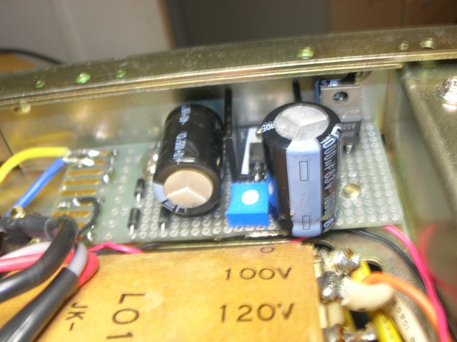
Fig. 19 – Posizionamento basetta alimentatore – Positioning of the power base
Ho usato un trasformatore toroidale allocato al posto della morsettiera del cambio tensione. Non ho trovato altro spazio disponibile.
I have used a toroid trasformer placed in place of the at the change of tension’s terminal. There was no other space.
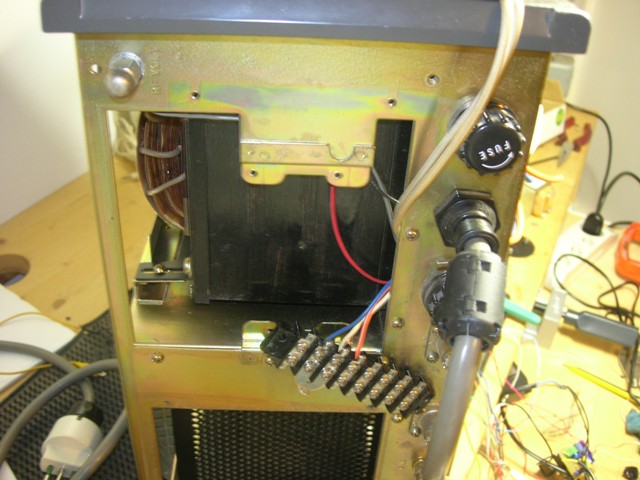 Fig. 20 – Rimozione commutatore di banda – Removal of the band switch
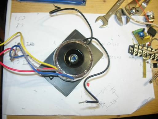 Fig. 21 – Montaggio trasformatore su coperchio cambio tensioni – Mounting the transformer on the change tensions cover
Ho ritenuto opportuno realizzare un piccolo testerino per testare che le commutazioni rispettino la tabella. Non si può rischiare errori. Ho usato una barra led recuperata nel solito cassetto e una manciata di resistenze da 1 k.
I thought it advisable to prepare a small tester to test the switch are in line with the table. You cannot risk errors. I used a led bar and some resistances at 1k
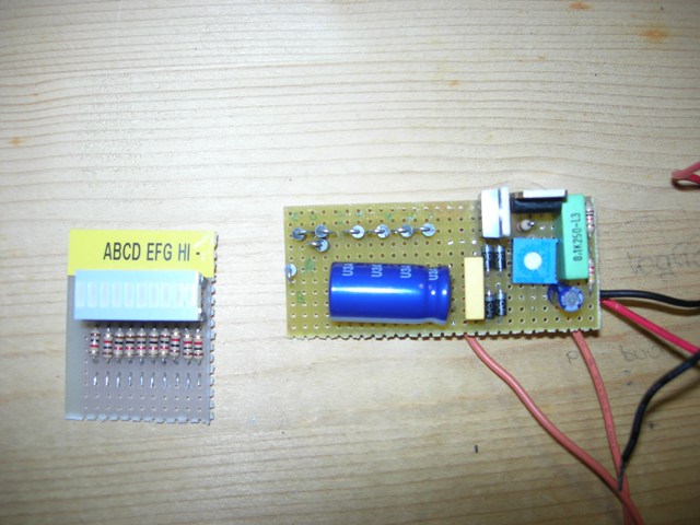 Fig. 22– Testerino e alimentatore a 26v di test – tester and 26v power for testing
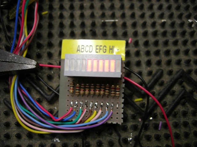
Fig.18 – Testerino in posizione 15m – Tester in 15m position
Collegare il testerino all’alimentazione (26,5V), saldare i fili al contatto normalmente aperto dei relè rispettando A con A, B con B, e così via.
Ruotare il commutatore e verificare che si accendano i led come da tabella. Dissaldare i fili ad uno ad uno e saldare al loro posto il collegamento corrispondente della bobina o dei condensatori.
Occorre prestare molta attenzione per non fare corti ed errori. Numerate con un pennarello i condensatori e le bobine. Il relè ”D” è stato cablato “in aria” direttamente sul condensatore d’antenna.
Connect the tester at 26,5V, weld the cables at the open contact of the relè following A with A, B with B etc. Rotate to switch a verify that the led turn on as per table. Disconnect the cables and weld the corresponding connection of the coils or of the capacitor.
Pay attention in order to avoid short-circuit and mistakes. Number with a pen the condensers and the coils. Relè “D” has been cabled “on air” directly to the antenna capacitor
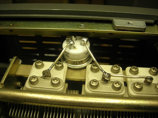 Fig. 19 – Posizione relè D – Position of relè D
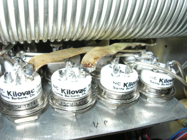
Fig. 20 – Alcune saldature bobine e condensatori – Some weldings of coils and capacitor
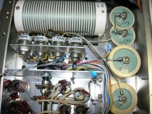
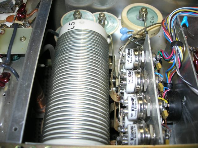
Fig. 23 – Collegamenti terminati, rimane da fascettare e sistemare i cavetti di alimentazione. – Connection concluded, you need to cover a place all power cables
Non ci resta che montare i relè per le commutazioni d’antenna e cablare ingresso e uscita.
Dalla foto si può notare che sono stati montati due diversi relè, un Kilovac e un Jennings.
Io avevo quest’ultimo nel solito cassetto è ho voluto provare a controllare i tempi di commutazione con un oscilloscopio. Ho riscontrato che il Jennings era di un paio di ms più veloce (non è una regola ma un caso) e ho optato per montarlo lato antenna. Si può notare cablatura in aria, montaggio dell’impedenza e scaricatore sui contatti. Non montate il cavo nero d’ingresso in questo modo, ma sostituitelo con un altro pezzetto di rg-58 e fatelo passare più in alto. Infatti, in fase di collaudo in posizione 160m sfiammava verso il condensatore sottostante.
It only remains to mount the relè of the switching of the antenna and cable in and out. From the photo you can note that two different relè has been mounted: one Kilovac and one Jennings. I had this already and I wanted to try the switch timings with an oscilloscope. I noted the Jennings one was a couple of ms faster (it is not a rule but probably the chance) and I mounted it on the side of the antenna. You can see the cabling “on air”, mounting of impedance and download on the contacts. Do not mount the in line black cable in this way but substitute with a piece of rg-58 and pass it over at higher height. When I tried it at position 160m was blazing in the condenser underneath.
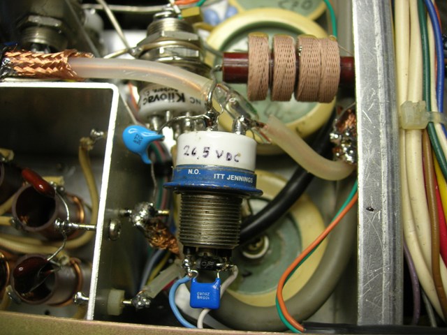 Fig. 24 – Relè d’antenna – Antenna relais
Il Kilovac è saldato direttamente sul pin di uscita del box d’ingresso e fissato tramite un supporto in filo argentato allo schermo sempre dello stesso. In questo modo ho creato una struttura portante per tutto l’insieme.
Ho inoltre montato il relè per la commutazione delle lampadine Tx /Rx e zener di bias a fianco della basetta di supporto dello zener, usando la stessa come punto di ancoraggio e un po’ di adesivo tra relè e base di alluminio.
The Kilovac is welded directly on the outline pin of the inline box and fixed by way of a silver cable on the screen. In this way I created a supporting structure.
I have also mounted at the switch relè some lights Tx/Rx and zener of bias on the side of the aluminium base.
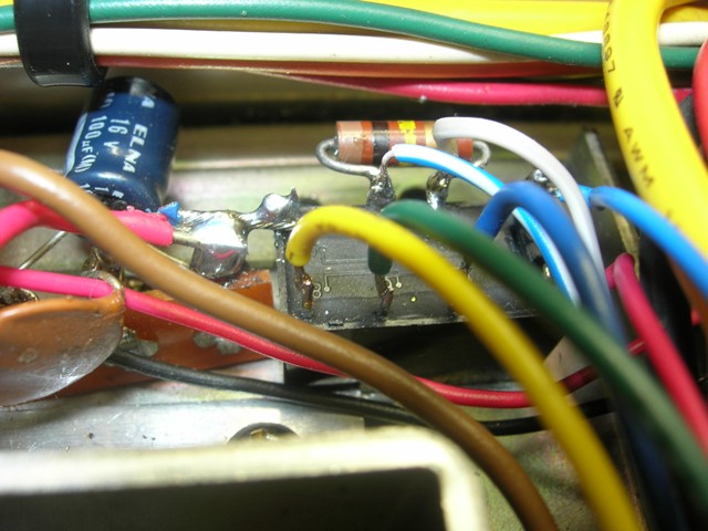
Fig. 25 – Relè zener – zener relè
Non mi assumo nessuna responsabilità sia per la buona riuscita della modifica che degli eventuali danni a persone o cose. Le tensioni in gioco sono molto alte e pericolose, potrebbero anche causare la morte.
I do not take any liability for the correct modification and for any damage and or injuries. The tensions we are dealing with are very high and can cause even the death.
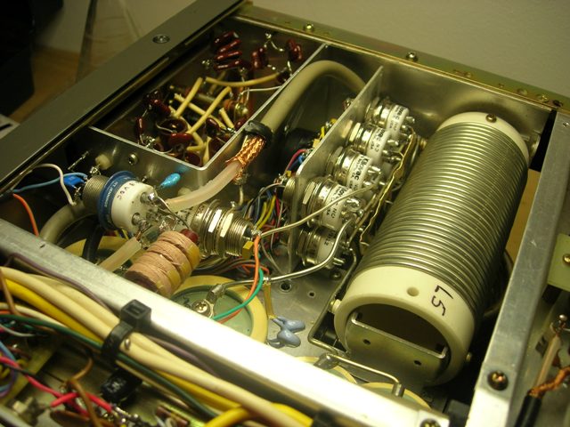
Alcune foto del lavoro terminato
Some photos
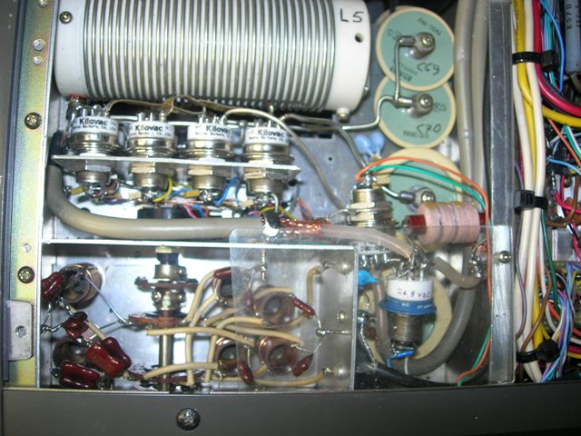
Si può notare un foglio di plexiglas che copre i relè di uscita, ho voluto isolare un po’ meglio questa parte dal panello di chiusura del fondo. Se lo fate anche voi, non esagerate con le dimensioni, il panello e forato e non dobbiamo chiudere la circolazione di aria. Si può anche vedere l’RG-58 del circuito d’ingresso sostituito.
You will note the Plexiglas sheet to cover the relè, I wanted to isolate this part in a better way from the bottom panel. I suggest not to exaggerate with its dimension in order not to compromise the cooling air circulation. You can also see the substituted RG-58.
Un paio di foto di altre modifiche ampiamente documentate in internet. Some other photo
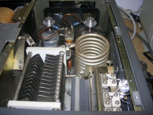
Ho provato a rimontare le bobine originali sull’anodo, dopo aver sostituito le resistenze, e non ho riscontrato nessun problema. Probabilmente questa modifica ha migliorato la stabilità di tutto l’insieme.
I tried to mount again the original coils on the anode after having substited the resistances and I have not noted any problem. This change has probably improved the stability of the whole system.
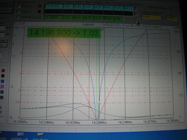
Per curiosità ….. Ros rilevato col mini VNA collegato sull’uscita del P.A. in 20m – Grafic response in 20m band measured with MINI-VNA
Un po’ di cifre. – Some details
Il costo del materiale per la modifica non ha superato i 200,00 euro, ovviamente con relè surplus.
The costs of the material for this modification is lower that Euro 200.
Le ore necessarie … ho perso il conto Hi
Potenza Out key down
70 Watt in 1400/1500 Watt out in tutte le bande ad esclusione dei 10m dove per avere la stessa lettura ho dovuto portare la potenza a in ingresso a 85 Watt.
Queste misure sono state effettuate con wattmetro passante e su carico fittizio. Prima della modifica non avevo mai letto una potenza superiore ai 1100 Watt.
Power Out key down
70 Watt in 1400/1500 Watt out in all band except 10m band were for 1400 w out the input is 85 Watt.
Measured on power lead.
Buon divertimento – Good luck
Tutto molto interessante infatti sto modificando il mio 922 ,ma a riguardo il condensatore variabile sotto vuoto non dici la tensione di lavoro , io ne ho visti 5-250 a 5Kv ma non so se vanno bene.
Quello che ho usato io è un Jennings da 4-250 Pf 5Kv, lo puoi desumere dalla foto. Nella mia precedente risposta ti avevo detto che no lo ricordavo, ma riguardando la foto il 5S che vedi è appunto il valore dei Kv.Se fai qualche ricerca puoi averne conferma. Ti assicuro che funziona.
Un’isolamento più alto porta ad un considerevole aumento delle dimensioni e non so come possa starci.